
Power Distribution and Efficiency: The Foundation of Reliable Data Center Operations
August 10, 2026
Power as Foundation
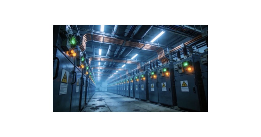
Power infrastructure is the foundation on which all data center operations rest. No matter how sophisticated the compute hardware, how advanced the cooling systems, or how intelligent the orchestration, without reliable power delivery, data centers cease functioning. In 2026, this fundamental truth faces unprecedented challenges as AI workloads drive power consumption to levels that test electrical infrastructure designed for traditional compute workloads. The transformation extends beyond simple capacity increases. It requires a fundamental reimagining of how power systems are designed, deployed, and integrated with both facility infrastructure and the broader electrical grid.
The global data center UPS market reflects this transformation, projected to grow from $8.76 billion in 2025 to $12.47 billion by 2030, representing a CAGR of 7.3%. This growth isn’t merely about scale, it reflects fundamental changes in technology adoption, architectural approaches, and operational strategies. The shift towards high-density AI computing, integrated liquid cooling, modular deployment models, and renewable energy mandates requires reimagining power architecture from utility connection through final rack-level delivery.
The challenge extends far beyond data center walls into the broader electrical grid infrastructure. Power availability is now the primary constraint on AI infrastructure deployment globally, with more than 36 projects worth $162 billion blocked or significantly delayed by electrical grid limitations. The core paradox of 2026 infrastructure planning: modern data centers can be designed and built in 12-24 months, but expanding electrical grid capacity to support them can take a decade.
This timing mismatch fundamentally reshapes industry strategy, forcing organizations to consider on-site generation, strategic site selection near existing grid capacity, alternative energy sources including nuclear power, and novel approaches to power sourcing that would have been considered impractical just five years ago. The organizations that successfully navigate these constraints will establish competitive advantages measured in years of time-to-market leadership while competitors await grid capacity expansion.
Understanding Power Requirements
Calculating Total Power Needs

Power planning begins with accurate load estimation across all facility systems, requiring detailed analysis of current requirements and realistic growth projections. IT equipment, including servers, storage arrays, networking infrastructure, GPU accelerators, and other compute equipment, are the largest single draw of power. In traditional enterprise data centers, IT load typically accounts for 60-70% of total facility power consumption. AI facilities implementing advanced liquid cooling push this ratio significantly higher, reaching 75-85% as cooling efficiency improvements reduce non-IT overhead proportionally.
Cooling infrastructure is typically the second-largest power consumer in most facilities, typically accounting for 20-30% of total facility load in conventional air-cooled environments. Advanced liquid cooling technologies can reduce this proportion to 10-15%, fundamentally improving Power Usage Effectiveness (PUE) metrics while enabling higher rack densities within existing building envelopes. The shift from air to liquid cooling doesn’t just reduce cooling power consumption — it fundamentally restructures facility power distribution requirements, enabling higher-density deployments within existing electrical capacity constraints that would be impossible with traditional air-cooling approaches.
Supporting infrastructure, such as lighting systems, building management platforms, security systems, fire suppression controls, elevator systems, and administrative office spaces, consume the remaining capacity, typically 5-10% of the total facility load. While seemingly minor compared to IT and cooling loads, these auxiliary systems require careful integration with emergency power systems to maintain basic facility operations, life safety systems, physical security, and critical monitoring capabilities during grid outages that could last hours or even days in extreme weather scenarios or grid emergencies.
The mathematics prove unforgiving in practice. A facility targeting 10 megawatts of IT capacity with PUE of 1.3 requires 13 megawatts of utility power delivery capacity. At 1.5 PUE, requirements jump to 15 megawatts. This 2-megawatt difference may seem modest, but actually has profound implications. After 10 years of continuous operation, this PUE difference represents 175 gigawatt-hours of additional electricity consumption costing $15-20 million at typical commercial electricity rates of $0.10-0.12/kWh. This substantial financial impact demonstrates why efficiency optimization delivers both environmental sustainability benefits and compelling economic returns that rapidly justify significant capital investment in high-efficiency infrastructure components.
Growth Planning and Scalability
Accurate capacity planning requires understanding not only current operational needs but also realistic growth trajectories over 5-10 year planning horizons that align with typical facility investment lifecycles. Under provisioning electrical infrastructure requires expensive retrofits as demand grows, often leading to partial or complete facility shutdowns during major electrical work that disrupts revenue-generating operations. Conversely, over provisioning wastes precious capital on unused capacity that sits idle for years, while simultaneously reducing operational efficiency by operating systems far below optimal load points, where efficiency peaks.
Modular electrical distribution enables incremental capacity additions that align precisely with actual demand growth patterns rather than speculative forecasts. Rather than installing complete electrical infrastructure for projected ultimate capacity from day one, which ties up capital in unused assets that generate no return, modular approaches deploy baseline capacity initially, with pre-engineered expansion modules added systematically as utilization increases and business growth justifies additional investment. This strategy optimizes capital deployment timing while maintaining expansion flexibility to accommodate changing business requirements, unexpected growth acceleration, or strategic pivots in service offerings.
AI workload growth dramatically increases planning complexity compared with traditional IT infrastructure expansion patterns. Traditional enterprise compute workloads grew relatively predictably, 5-10% annually as businesses expanded organically through normal market growth. AI deployments can increase compute requirements by 50-100% within 12 months as organizations rapidly scale from limited pilot projects to full production deployments serving millions of users. Electrical infrastructure must accommodate this growth volatility without requiring disruptive facility-wide shutdowns for capacity additions that interrupt revenue-generating operations and damage customer relationships.
UPS Systems and Redundancy Models
UPS Technology Evolution

Uninterruptible Power Supply (UPS) systems are the critical bridge between utility power failure and backup generator start-up, maintaining continuous power to critical loads throughout the transition. Modern UPS systems have evolved from simple backup battery arrays with basic inverters into sophisticated power management platforms that integrate with facility-wide energy optimization strategies, participate in utility demand response programs, provide granular power quality monitoring, and deliver valuable telemetry data for predictive maintenance algorithms.
Three primary UPS topologies meet different application requirements, each with distinct trade-offs among efficiency, power quality, and cost. An online double-conversion UPS continuously converts incoming AC utility power to DC for battery charging and energy storage, then inverts DC back to clean AC for equipment power delivery. This topology provides perfect isolation from utility power quality issues including voltage sags, surges, harmonics, frequency variations, and transients. However, it historically suffers a 5-10% efficiency penalty due to dual conversion losses, generating substantial waste heat that requires additional cooling capacity.
Modern high-efficiency UPS systems achieve 96-98% efficiency in double-conversion mode through advanced power electronics utilizing silicon carbide semiconductors, sophisticated digital control algorithms, and intelligent bypass modes that dynamically optimize conversion paths based on real-time power quality assessment. Eco-mode technology, for example, delivers up to 99% efficiency by keeping equipment on utility power during clean power conditions, continuously monitoring at millisecond intervals, and transferring seamlessly to battery backup within 2-4 milliseconds when power quality degradation is detected. This 2-4% efficiency improvement translates to a PUE reduction of 0.02-0.04 representing 1-2 million kWh savings annually for typical 20-30 megawatt facilities.
Lithium-ion batteries are rapidly displacing traditional valve-regulated lead-acid (VRLA) batteries in UPS applications despite higher initial costs. Lithium-ion offers a 3-5x longer operational lifespan (10-15 years versus 3-5 years for VRLA), a 50-70% smaller physical footprint for equivalent energy capacity, enabling more compact installations, significantly faster recharge times, enabling rapid recovery after utility outages, superior performance across a wider temperature range, reducing cooling requirements, and minimal capacity degradation over the service life. The higher upfront capital cost, typically 2-3x lead-acid pricing, is offset by reduced replacement frequency, lower cooling requirements, improved reliability, and enhanced operational flexibility over 10-15-year facility lifecycles, making the total cost of ownership favorable for lithium-ion in most applications.
Redundancy Architectures

Redundancy design determines facility resilience against power system component failures and maintenance requirements. The industry employs standardized nomenclature to describe redundancy levels with precise meanings: N represents the minimum capacity required for facility operation at full design load; +1 indicates one additional redundant component providing single-failure tolerance; and 2N indicates complete duplication of all power infrastructure, providing full-path redundancy.
The N+1 configuration provides tolerance for single-component failures without service interruption or performance degradation. A facility requiring four UPS modules to handle the full IT load deploys five modules of equivalent capacity, ensuring operations continue seamlessly even if one module fails unexpectedly or requires scheduled maintenance. This approach balances capital cost efficiency with reliability requirements for many enterprise deployments, where brief scheduled maintenance windows are acceptable for non-critical systems and contractual uptime requirements permit occasional planned downtime with advance customer notification.
2N (fully redundant) architecture duplicates the entire power distribution path from the utility grid connection through UPS systems, automatic transfer switches, power distribution units, and final delivery to equipment racks. Each IT load connects to dual independent power supplies, each fed from completely separate UPS systems, utility connections, backup generators, and distribution networks, with no shared single points of failure. This configuration survives the complete failure of any single power path, including loss of the entire utility feed, generator failure, UPS system collapse, or even a catastrophic fire destroying one electrical room, without any impact on IT operations or customer service levels. 2N+1 adds an additional redundancy layer to a fully redundant architecture, as each redundant power path includes N+1 component capacity rather than the minimum of N. This premium design tolerates multiple simultaneous failures across both power paths and enables invasive maintenance on either complete power path without reducing facility redundancy levels or increasing failure risk during maintenance windows. Hyperscale operators and mission-critical facilities supporting financial trading platforms, healthcare systems, emergency services, or other applications where even milliseconds of downtime create substantial financial or safety consequences justify the substantial additional capital expenditure through near-perfect uptime, routinely delivering availability exceeding 99.999%.
Grid-Interactive UPS
An emerging trend positions UPS systems as active grid stabilization assets rather than purely passive backup systems isolated from utility operations. Grid-interactive UPS installations can discharge stored battery energy back into utility grids during peak demand periods, providing grid operators with valuable, fast-responding load-balancing capacity while generating ancillary revenue streams for data centre operators through participation in wholesale electricity markets and demand response programs.
Microsoft, Google, Amazon, and other hyperscalers are pioneering these implementations, treating multi-megawatt UPS battery capacity as distributed energy resources that actively participate in real-time electricity markets. During utility peak demand periods, when wholesale electricity prices spike dramatically, sometimes reaching $1,000+ per megawatt-hour during heat waves or other stress events, facilities export stored energy at premium rates. During off-peak periods with lower pricing, facilities recharge batteries at reduced cost, often at night when renewable generation exceeds demand. The arbitrage opportunity, combined with capacity payments and demand response incentives from utilities desperate for grid flexibility, can generate hundreds of thousands of dollars annually for large facilities while reducing grid stress.
Energy Efficiency and PUE Optimization
High-Efficiency Power Distribution
Power distribution inefficiency compounds across multiple transformation stages, from the utility delivery voltage to the final equipment consumption voltage. Each voltage transformation step, every meter of conductor run, and all electrical connections and switching gear introduce resistive losses that waste energy as heat and reduce the power available for productive IT workloads. Traditional data centers distributed 480V three-phase power to row-level distribution panels, step it down to 208V at rack PDUs (Power Distribution Units), and then further reduce it to 120V for equipment requiring single-phase power. Each transformation step loses 2-5% efficiency through transformer core and winding losses combined with conductor resistance. Three sequential transformation stages mean 6-15% cumulative losses before power reaches IT equipment. This wastes substantial energy and generates unwanted heat that cooling systems must then remove, creating a vicious cycle of inefficiency.
Modern high-efficiency distribution architectures minimize transformation stages and optimize conductor sizing for actual load characteristics. Direct 480V distribution to high-efficiency rack PDUs eliminates row-level transformation entirely, removing one complete loss stage. Rack PDUs achieving 97-98% efficiency through high-quality transformers, optimized magnetic design, and superior components minimize unavoidable final transformation losses. Properly sized conductors, neither undersized causing excessive I²R resistance losses or oversized wasting copper material and conduit space, balance efficiency optimization against capital costs and installation practicality.
Renewable Energy Integration

Major technology companies are partnering with renewable energy developers to secure clean power for data center operations through increasingly sophisticated financial and contractual arrangements. Power Purchase Agreements (PPAs) guarantee electricity consumers stable pricing over 10-25 year contract terms while providing renewable energy developers with revenue certainty that makes new generation projects financially viable and bankable for project financing. Data centers, with predictable high-volume electricity consumption operating 24/7/365, represent ideal PPA customers.
Geographic considerations significantly complicate PPA execution in practice. Renewable generation patterns don’t necessarily align with consumption patterns. Solar production peaks at midday, while data centers consume power continuously 24/7. Wind generation varies with meteorological conditions rather than with computational workload demands. Grid infrastructure must reliably transport power from generation locations to consumption facilities, introducing transmission capacity constraints, distance-related losses of 2-5% per hundred miles, and wheeling charges that materially affect project economics.
Infrastructure Challenges and Solutions
The Power Paradox

The “Power Paradox” describes the critical mismatch in timing between data center construction cycles and electrical utility grid capacity expansion timelines. Modern data centers deploy in 12-24 months from initial groundbreaking to full operational status, using modular construction techniques, prefabricated components, and parallel work streams. Electrical utility grid expansions including new high-voltage transmission lines, distribution substations, interconnection infrastructure, and grid modernization, require 5-10 years because of complex permitting processes, lengthy land acquisition negotiations, environmental impact reviews, regulatory approvals at multiple government levels, community opposition, and physical construction.
This fundamental mismatch creates devastating strategic bottlenecks that limit industry growth. Organizations can successfully secure land, complete facility designs, procure equipment worth hundreds of millions, and finish construction only to discover that electrical grid capacity remains unavailable for years beyond planned opening dates, leaving expensive facilities sitting idle, generating no revenue. Major global markets, including Dublin, Amsterdam, Singapore, and parts of Northern Virginia, have already implemented connection moratoriums or severe restrictions due to grid capacity exhaustion from data center concentration.
Near-term solutions involve strategically co-locating data centers with existing high-capacity electrical infrastructure rather than greenfield sites requiring extensive grid expansion. Former industrial facilities, retired power plant locations, aluminum smelters, and proximity to major transmission substations offer immediate, substantial grid capacity, avoiding years of infrastructure development delays. While these locations may compromise other site-selection criteria like fiber connectivity, labor availability, or natural disaster risk, immediate power availability often outweighs other considerations in 2026’s constrained environment.
Conclusion
Power infrastructure determines data center capability and operational reliability more fundamentally than any other facility system. In 2026, power availability — not physical space, cooling capacity, or even equipment procurement costs — will be the primary constraint on AI infrastructure deployment globally. Organizations succeeding in this constrained environment are those that recognized early that power infrastructure demands equal strategic attention to compute capability. The future belongs to facilities treating power infrastructure as a strategic differentiator. The focal point is to optimize efficiency, maximize reliability through thoughtful redundancy, integrate intelligently with renewable energy and broader grid systems, and develop alternative sourcing strategies that reduce dependence on increasingly constrained public grid infrastructure to create sustainable, resilient operational foundations supporting the next decade of AI advancement.